If a Harvester node becomes unreachable, Harvester attempts to reschedule its virtual machines to another healthy node. However, this rescheduling doesn't happen immediately. The associated virt-launcher pods may continue to appear to remain in the ready state due to its KubeVirt readiness gate configuration.
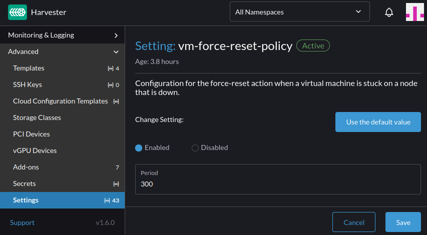
To mitigate this elapsed time, you can modify the vm-force-reset-policy setting, by reducing its period value. This enables Harvester to detect non-ready virtual machines on unreachable nodes sooner.
This setting can be found in the Advanced -> Settings page on the Harvester UI.
Additionally, while the current default is 5 minutes, we are considering reducing the default value [1].
Harvester allows you to add disks as data volumes. However, only disks that have a World Wide Name (WWN) are displayed on the UI. This occurs because the Harvester node-disk-manager uses the ID_WWN value from udev to uniquely identify disks. The value may not exist in certain situations, particularly when the disks are connected to certain hardware RAID controllers. In these situations, you can view the disks only if you access the host using SSH and run a command such as cat /proc/partitions.
To allow extra disks without WWNs to be visible to Harvester, perform either of the following workarounds:
Use this method only if the provisioner of the extra disk is Longhorn V1, which is filesystem-based. This method will not work correctly with LVM and Longhorn V2, which are both block device-based.
When you create a filesystem on a disk (for example, using the command mkfs.ext4 /dev/sda), a filesystem UUID is assigned to the disk. Harvester uses this value to identify disks without a WWN.
In Harvester versions earlier than v1.6.0, you can use this workaround for only one extra disk because of a bug in duplicate device checking.
Workaround 2: Add a udev rule for generating fake WWNs
note
This method works with all of the supported provisioners.
You can add a udev rule that generates a fake WWN for each extra disk based on the device serial number. Harvester accepts the generated WWNs because the only requirement is a unique ID_WWN value as presented by udev.
A YAML file containing the necessary udev rule must be created in the /oem directory on each host. This process can be automated across the Harvester cluster using a CloudInit Resource.
Create a YAML file named fake-scsi-wwn-generator.yaml with the following contents:
apiVersion: node.harvesterhci.io/v1beta1 kind: CloudInit metadata: name: fake-scsi-wwn-generator spec: matchSelector:{} filename: 90_fake_scsi_wwn_generator.yaml contents:| name: "Add udev rules to generate missing SCSI disk WWNs" stages: initramfs: - files: - path: /etc/udev/rules.d/59-fake-scsi-wwn-generator.rules permissions: 420 owner: 0 group: 0 content: | # For anything that looks like a SCSI disk (/dev/sd*), # if it has a serial number, but does _not_ have a WWN, # create a fake WWN based on the serial number. We need # to set both ID_WWN so Harvester's node-disk-manager # can see the WWN, and ID_WWN_WITH_EXTENSION which is # what 60-persistent-storage.rules uses to generate a # /dev/disk/by-id/wwn-* symlink for the device. ACTION=="add|change", SUBSYSTEM=="block", KERNEL=="sd*[!0-9]", \ ENV{ID_SERIAL}=="?*", \ ENV{ID_WWN}!="?*", ENV{ID_WWN_WITH_EXTENSION}!="?*", \ ENV{ID_WWN}="fake.$env{ID_SERIAL}", \ ENV{ID_WWN_WITH_EXTENSION}="fake.$env{ID_SERIAL}"
Apply the file's contents to the cluster by running the command kubectl apply -f fake-scsi-wwn-generator.yaml.
The file /oem/90_fake_scsi_wwn_generator.yaml is automatically created on all cluster nodes.
Reboot all nodes to apply the new udev rule.
Once the rule is applied, you should be able to view and add extra disks that were previously not visible on the Harvester UI.
Harvester 1.5 introduces support for the provisioning of virtual machine root volumes and data volumes using external Container Storage Interface (CSI) drivers.
This article demonstrates how to use Velero 1.16.0 to perform backup and restore of virtual machines in Harvester.
It goes through commands and manifests to:
Back up virtual machines in a namespace, their NFS CSI volumes, and associated namespace-scoped configuration
Export the backup artifacts to an AWS S3 bucket
Restore to a different namespace on the same cluster
Restore to a different cluster
Velero is a Kubernetes-native backup and restore tool that enables users to perform scheduled and on-demand backups of virtual machines to external object storage providers such as S3, Azure Blob, or GCS, aligning with enterprise backup and disaster recovery practices.
note
The commands and manifests used in this article are tested with Harvester 1.5.1.
The CSI NFS driver and Velero configuration and versions used are for demonstration purposes only. Adjust them according to your environment and requirements.
important
The examples provided are intended to backup and restore Linux virtual machine workloads. It is not suitable for backing up guest clusters provisioned via the Harvester Rancher integration.
To backup and restore guest clusters like RKE2, please refer to the distro official documentation.
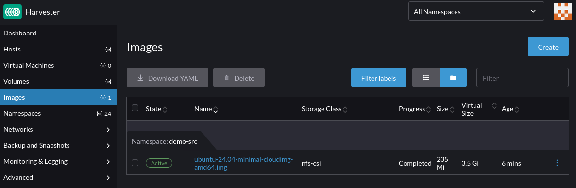
Confirm the virtual machine image is successfully uploaded to Harvester:
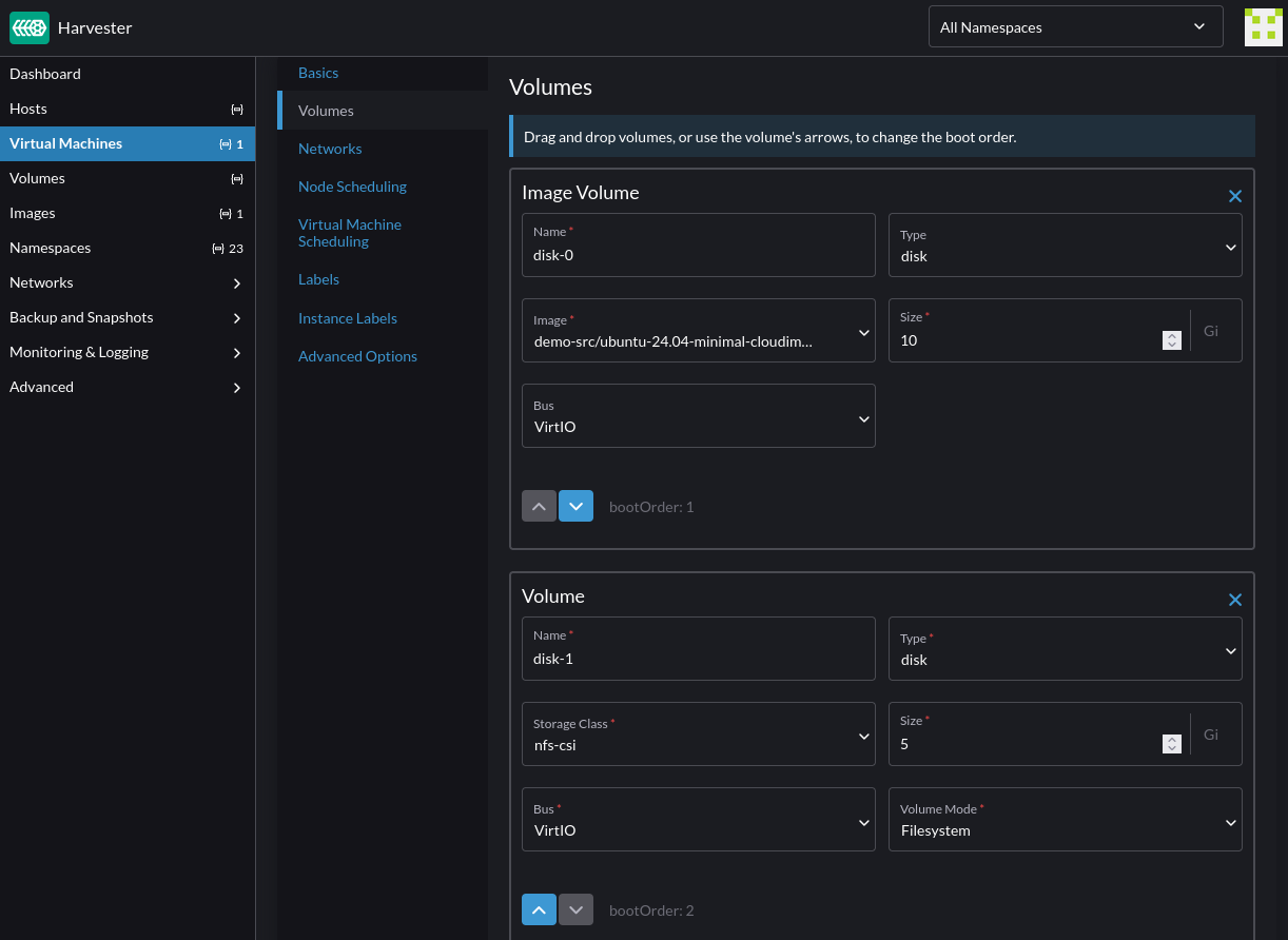
Follow the instructions in the third-party storage documentation to create a virtual machine with NFS root and data volumes, using the image uploaded in the previous step.
For NFS CSI snapshot to work, the NFS data volume must have the volumeMode set to Filesystem:
optional
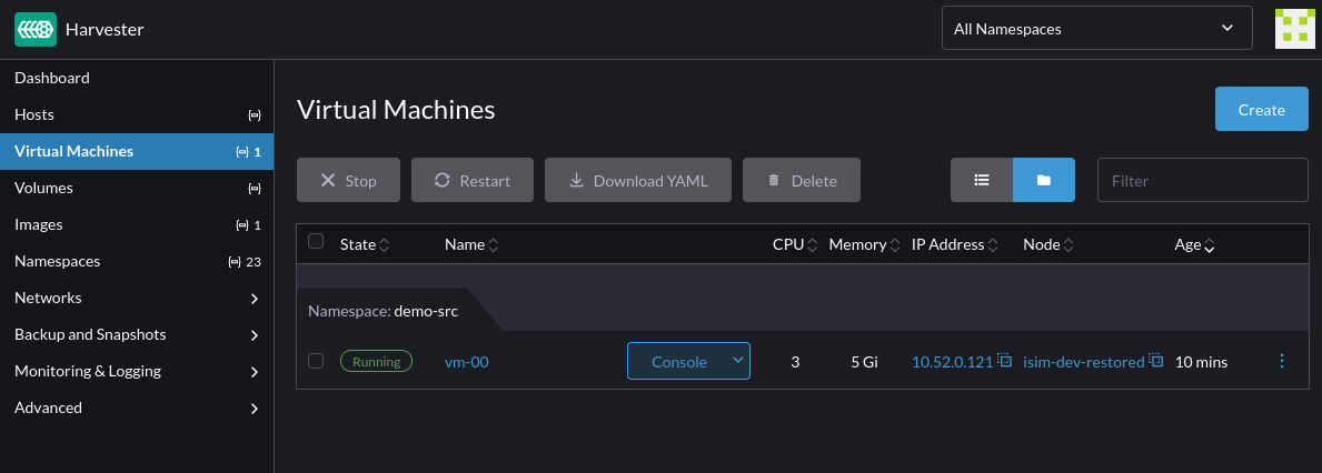
For testing purposes, once the virtual machine is ready, access it via SSH and add some files to both the root and data volumes.
The data volume needs to be partitioned, with a file system created and mounted before files can be written to it.
This creates a backup of the demo-src namespace containing resources like the virtual machine created earlier, its volumes, secrets and other associated configuration.
Depending on the size of the virtual machine and its volumes, the backup may take a while to complete.
The DataUpload custom resources provide insights into the backup progress:
kubectl -n velero get datauploads -l velero.io/backup-name="${BACKUP_NAME}"
Confirm that the backup completed successfully:
velero backup get "${BACKUP_NAME}"
NAME                         STATUS      ERRORS   WARNINGS   CREATED                         EXPIRES   STORAGE LOCATION   SELECTOR
backup-demo-src-1747954979   Completed   0        0          2025-05-22 16:04:46 -0700 PDT   29d       default            <none>
After the backup completes, Velero removes the CSI snapshots from the storage side to free up the snapshot data space.
tips
The velero backup describe and velero backup logs commands can be used to assess details of the backup including resources included, skipped, and any warnings or errors encountered during the backup process.
This restore modifier removes the harvesterhci.io/volumeForVirtualMachine annotation from the virtual machine data volumes to ensure that the restoration do not conflict with the CDI volume import populator.
Create the restore modifier:
kubectl -n velero create cm modifier-data-volumes --from-file=modifier-data-volumes.yaml
The virtual machine MAC address and firmware UUID are reset to avoid potential conflicts with existing virtual machines.
the virtual machine image manifest is excluded because Velero restores the entire state of the virtual machine from the backup.
the modifier-data-volumes restore modifier is invoked to modify the virtual machine data volumes metadata to prevent conflicts with the CDI volume import populator.
While the restore operation is still in-progress, the DataDownload custom resources can be used to examine the progress of the operation:
RESTORE_NAME=backup-demo-src-1747954979-20250522164015

kubectl -n velero get datadownload -l velero.io/restore-name="${RESTORE_NAME}"
Confirm that the restore completed successfully:
velero restore get
NAME                                        BACKUP                       STATUS      STARTED                         COMPLETED                       ERRORS   WARNINGS   CREATED                         SELECTOR
backup-demo-src-1747954979-20250522164015   backup-demo-src-1747954979   Completed   2025-05-22 16:40:15 -0700 PDT   2025-05-22 16:40:49 -0700 PDT   0        6          2025-05-22 16:40:15 -0700 PDT   <none>
Verify that the virtual machine and its configuration are restored to the new demo-dst namespace:
note
Velero uses Kopia as its default data mover. This issue describes some of its limitations on advanced file system features such as setuid/gid, hard links, mount points, sockets, xattr, ACLs, etc.
Velero provides the --data-mover option to configure custom data movers to satisfy different use cases. For more information, see the Velero's documentation.
tips
The velero restore describe and velero restore logs commands provide more insights into the restore operation including the resources restored, skipped, and any warnings or errors encountered during the restore process.
This section extends the above scenario to demonstrate the steps to restore the backup to a different Harvester cluster.
On the target cluster, install Velero, and set up the NFS CSI and NFS server following the instructions from the Deploy the NFS CSI and Example Server section.
Once Velero is configured to use the same backup location as the source cluster, it automatically discovers the available backups:
velero backup get
NAME                         STATUS      ERRORS   WARNINGS   CREATED                         EXPIRES   STORAGE LOCATION   SELECTOR
backup-demo-src-1747954979   Completed   0        0          2025-05-22 16:04:46 -0700 PDT   29d       default            <none>
By default, Velero only supports resource filtering by resource groups and labels. In order to backup/restore a single instance of virtual machine, custom labels must be applied to the virtual machine, and its virtual machine instance, pod, data volumes, persistent volumes claim, persistent volumes and cloudinit secret resources. It's recommended to backup the entire namespace and perform resource filtering during restore to ensure that backup contains all the dependency resources required by the virtual machine.
The restoration of virtual machine image is not fully supported yet.
Users wishing to prevent privilege escalation and other security issues can leverage Kubernetes' Pod Security Standards (PSS) on Harvester. PSS are a set of security policies that can be applied to clusters and namespaces to control and restrict how workloads are executed.
Pod Security Standards in Harvester can be used when provisioning VM workloads and also with the new experimental support for running baremetal container workloads.
The baseline policy is aimed at ease of adoption for common containerized workloads while preventing known privilege escalations. This policy is targeted at application operators and developers of non-critical applications.
warning
VMs with device passthrough, such as pcidevices, usbdevices and vgpudevices, will fail to start with baseline policy, as they need SYS_RESOURCE capability. This is being tracked on issue #8218. A fix should be available for this shortly.
Do not apply PSS to the system's namespaces, as they need privileged permissions to manage cluster resources. Only trusted users must have access to system's namespaces.
Cluster wide PSS can be enabled by passing an Admission Control configuration via kube-apiserver arguments. This can be done via Harvester's CloudInit using the following configuration which can be saved to cloudinit-pss.yaml file:
The cluster admin can apply this against the Harvester cluster using kubectl apply -f cloudinit-pss.yaml. The change requires a restart of the control plane nodes to ensure that the Elemental cloud-init directives are applied on boot. Once control plane nodes are rebooted, a default baseline pod security standard will be enforced against all current and subsequently created namespaces. The namespaces listed under exemptions will be skipped. Users are free to tweak the list, to better suit their use cases.
For future integration of Pod Security Admission (PSA) configuration natively in Harvester, please verify the progress of issue #8196.
Post application of a default PSS, end users, with permissions to create and edit namespaces, may still be able to override the respective policy by labeling their namespaces to support privileged workloads, for example, as follows:
To avoid this, we recommend users to create custom RBACs restricting who can create/update namespaces or to also deploy a Validating Admission Policy. The following policy will block namespace create/update requests containing a label pod-security.kubernetes.io/enforce, there by preventing namespace admins from changing the settings for their namespace.
In case more tailored policies are needed, users can rely on security policy engines like Kubewarden's policy PSA Label Enforcer, or similar solution, to ensure that namespaces have the required PSS configuration for deployment in the cluster.
CVE-2025-1974 (vector: CVSS:3.1/AV:N/AC:L/PR:N/UI:N/S:U/C:H/I:H/A:H) has a score of 9.8 (Critical).
The vulnerability affects specific versions of the RKE2 ingress-nginx controller (v.1.11.4 and earlier, and v1.12.0). All Harvester versions that use this controller (including v1.4.2 and earlier) are therefore affected.
This CVE is fixed in Harvester 1.5.0, 1.4.3 and newer.
A security issue was discovered in Kubernetes where under certain conditions, an unauthenticated attacker with access to the pod network can achieve arbitrary code execution in the context of the ingress-nginx controller. This can lead to disclosure of secrets accessible to the controller. (Note that in the default installation, the controller can access all secrets cluster-wide.)
You can confirm the version of the RKE2 ingress-nginx pods by running this command on your Harvester cluster:
kubectl -n kube-system get po -l"app.kubernetes.io/name=rke2-ingress-nginx" -ojsonpath='{.items[].spec.containers[].image}'
If the command returns one of the affected versions, disable the rke2-ingress-nginx-admission validating webhook configuration by performing the following steps:
On one of your control plane nodes, use kubectl to confirm the existence of the HelmChartConfig resource named rke2-ingress-nginx:
$ kubectl -n kube-system get helmchartconfig rke2-ingress-nginx
NAME                 AGE
rke2-ingress-nginx   14d1h
Use kubectl -n kube-system edit helmchartconfig rke2-ingress-nginx to add the following configurations to the resource:
The following is an example of what the updated .spec.valuesContent configuration along with the default Harvester ingress-nginx configuration should look like:
Exit the kubectl edit command execution to save the configuration.
Harvester automatically applies the change once the content is saved.
important
The configuration disables the RKE2 ingress-nginx admission webhooks while preserving Harvester's default ingress-nginx configuration.
If the HelmChartConfig resource contains other custom ingress-nginx configuration, you must retain them when editing the resource.
Verify that RKE2 deleted the rke2-ingress-nginx-admission validating webhook configuration.
$ kubectl get validatingwebhookconfiguration rke2-ingress-nginx-admission
Error from server (NotFound): validatingwebhookconfigurations.admissionregistration.k8s.io "rke2-ingress-nginx-admission" not found
Verify that the ingress-nginx pods are restarted successfully.
$ kubectl -n kube-system get po -lapp.kubernetes.io/instance=rke2-ingress-nginx
NAME                                  READY   STATUS    RESTARTS   AGE
rke2-ingress-nginx-controller-g8l49   1/1     Running   0          5s
Once your Harvester cluster receives the RKE2 ingress-nginx patch, you can re-install the rke2-ingress-nginx-admission validating webhook configuration by removing the HelmChartConfig patch.
important
These steps only cover the RKE2 ingress-nginx controller that is managed by Harvester. You must also update other running ingress-nginx controllers. See the References section for more information.
The ISO image may fail to boot when you attempt to install Harvester on a host with the following characteristics:
An operating system was previously installed, particularly openSUSE Leap 15.5 or later and Harvester v1.3.1 or later. Other Linux distributions and recent versions of Windows may also be affected.
UEFI secure boot is enabled.
This issue occurs when the Harvester ISO uses a shim bootloader that is older than the bootloader previously installed on the host. For example, the Harvester v1.3.1 ISO uses shim 15.4 but the system uses shim 15.8 after installation, which sets SBAT revocations for older shims. Subsequent attempts to boot the older shim on the ISO fail with the following error:
Verifying shim SBAT data failed: Security Policy Violation
Something has gone seriously wrong: SBAT self-check failed: Security Policy Violation
To mitigate the issue, perform the following workaround:
Disable Secure Boot.
Boot the ISO image and proceed with the installation.
Enable Secure Boot and boot into the installed system.
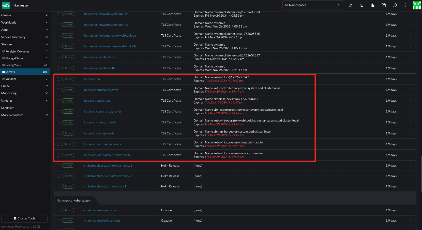
Harvester's embedded Rancher UI may display warnings about expiring KubeVirt certificates. You can safely ignore these warnings because automatic certificate rotation is handled by KubeVirt and is enabled by default.
KubeVirt provides a self-signed certificate mechanism that rotates both CA and certifcates on a defined recurring interval. You can check the setting certificateRotateStrategy by running the following command:
kubectl get kubevirt -n harvester-system -o yaml
By default, the value of certificateRotateStrategy is empty, which means that KubeVirt uses its default rotation settings and no manual configuration is required.
You can use the following fields to configure certificateRotateStrategy.
.ca.duration: Validity period of the CA certificate. The default value is "168h".
.ca.renewBefore: Amount of time before a CA certificate expires during which a new certificate is issued. The default value is "33.6h".
.server.duration: Validity period of server component certificates (for example, virt-api, virt-handler, and virt-operator). The default value is "24h".
.server.renewBefore: Amount of time before a server certificate expires during which a new certificate is issued. The default value is "4.8h".
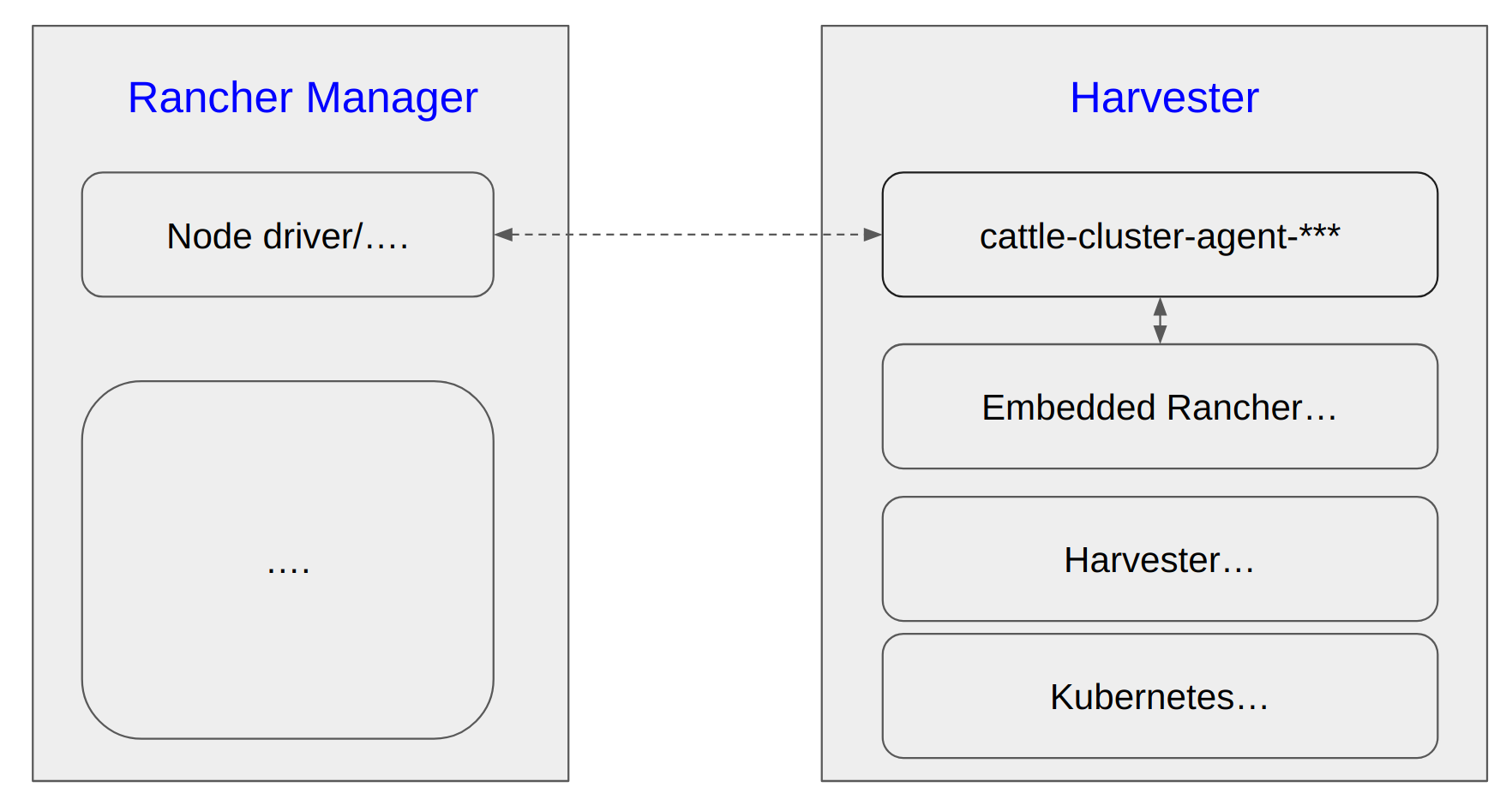
The Rancher Manager/Server is deployed independently. (Hereafter it is mentioned as Rancher Manager)
The Harvester cluster is imported to this Rancher Manager and works as a node driver.
The Rancher Manager deploys a couple of downstream K8s clusters, the machines/nodes of those clusters are backed by Harvester VMs.
There are also some traditional VMs deployed on the Harvester cluster, which have no direct connection with the Rancher Manager.
You plan to move those Harvester nodes geographically, or to power off the whole cluster for some time, it is essential to shutdown the Harvester cluster and restart later.
note
2 3 4 are optional if your Harvester cluster is mainly running as an IaaS component. This instruction covers all the above scenarios.
To safely shutdown a Harvester cluster, you need to follow the roughly reverse order of the cluster installation and the workload deployments.
Those facts need to be taken into account particularly:
The common methodology of Kubernetes operator/controller is to try things continuously until they meet expectations. When the cluster is shutting down node by node, if you don't stop those workloads in advance, they will try hard until the last node is off. It causes the last few nodes to have heavy CPU/memory/network/storage usage and increases the chance of data corruption.
Each Harvester node has limited capacity of CPU/memory/network/storage and the max-pod-number, when all workloads are crowded on the last few nodes, the unexpected pod eviction, scheduling failure and other phenomena may happen.
Harvester has embedded Longhorn as the default CSI driver, each PV can have 3 or more replicas, when replicas are rescheduled to other nodes, Longhorn will copy data from source node and rebuild the replica. Undoubtedly, stop the PVs as much as possible before the cluster shutdown to avoid the data moving.
Unlike normal Kubernetes deployments which have no PVs and are more flexible & agile to deploy anywhere on the cluster, the VMs are backed by massive sized PVs, slowly to move/migrate or even pinned on certain nodes to take the advantage of PCI-passthrough/vGPU/... and are much more sensitive to data consistency.
Needless to say, it is a bad practice to brutally power off the nodes on production environments.
For trouble-shooting purpose, it is essential to follow this instruction to generate a support-bundle file before taking any actions. And make sure the workload namespaces are added.
Harvester cluster is built on top of Kubernetes, a general requirement is that the Node/Host IP and the cluster VIP should keep stable in the whole lifecycle, if IP changes the cluster may fail to recover/work.
If your VMs on Harvester are used as Rancher downstream cluster machines/nodes, and their IPs are allocated from DHCP server, also make sure those VMs will still get the same IPs after the Harvester cluster is rebooted and VMs are restarted.
A good practice is to have detailed documents about the infrastructure related settings.
The bare metal server NIC slot/port connections with the remote (ToR) Switches.
The VLAN for the management network.
(Optional) The DHCP Server, ip-pools and ip-mac bindings for the Harvester cluster if DHCP server is used. If there is no fixed IP binding, when the server restarts after some days it may get a different IP from the DHCP server.
It is always a good practice to backup things before a whole cluster shutdown.
(Optional) Backup Downstream K8s Clusters if Possible
Harvester doesn't touch the (Rancher Manager managed) downstream K8s clusters' workload, when they are not able to be migrated to other node drivers, suggests to backup those clusters.
(Optional) Stop or Migrate Downstream K8s Clusters if Possible
Harvester doesn't touch the downstream K8s clusters' workload, but suggests to stop or migrate the downstream clusters to avoid your service interruption.
When Rancher deploys a downstream cluster on node driver Harvester, it creates a couple of VMs on Harvester automatically. Directly stopping those VMs on Harvester is not a good practice when Rancher is still managing the downstream cluster. For example, Rancher may create new VMs if you stop them from Harvester.
note
This depends on the auto-replace and/or other options on Rancher Manager.
If you have got a solution to shutdown those downstream clusters, and check those VMs are Off; or there is no downstream clusters, then jump to the step disable some addons.
Unless you have already deleted all the downstream clusters which are deploy on this Harvester, DO NOTremove this imported Harvester from the Rancher Manager. Harvester will get a different driver-id when it is imported later, but those aforementioned downstream clusters are connected to driver-id.
To safely shutdown those VMs but still keep the Rancher Manager managed downstream cluster alive, please follow the steps below:
Harvester has an embedded Rancher deployment which is used to help the lifecycle management of Harvester itself, it is different from the independently deployed Rancher Manager for multi-cluster management and more.
The cattle-cluster-agent-*** pod is the direct connection between Rancher Manager and Harvester cluster, and this pod is monitored and managed by the embedded Rancher in Harvester, scaling down this pod does not work. The embedded Rancher will scale it up automatically.
Run steps below to suspend the connection.
All following CLI commands are executed upon Harvester cluster.
Set the management.cattle.io/scale-available of deployment rancher to be "" instead of "3" or other values.
This change will stop the auto-scaling.
harvester$ kubectl edit deployment -n cattle-system rancher
apiVersion: apps/v1
kind: Deployment
metadata:
  annotations:
...
    management.cattle.io/scale-available: "3"  // record this value, and change it to ""
...
  generation: 16
  labels:
    app: rancher
    app.kubernetes.io/managed-by: Helm
...
  name: rancher
  namespace: cattle-system
Scale down the rancher deployment.
harvester$ kubectl scale deployment -n cattle-system rancher --replicas=0
deployment.apps/rancher scaled


harvester$ get deployment -n cattle-system rancher
NAME      READY   UP-TO-DATE   AVAILABLE   AGE
rancher   0/0     0            0           33d
Make sure the rancher-* pods are gone.
Check the rancher-* pods on cattle-system are gone, if any of them is stucking at Terminating, use kubectl delete pod -n cattle-system rancher-pod-name --force to delete it.
harvester$ kubectl get pods -n cattle-system
NAME                                         READY   STATUS        RESTARTS       AGE
..
rancher-856f674f7d-5dqb6                     0/1     Terminating   0              3d22h
rancher-856f674f7d-h4vsw                     1/1     Running       23 (68m ago)   33d
rancher-856f674f7d-m6s4r                     0/1     Pending       0              3d19h
...
Scale down the cattle-cluster-agent deployment.
harvester$ kubectl scale deployment -n cattle-system cattle-cluster-agent --replicas=0
deployment.apps/cattle-cluster-agent scaled


harvester$ kubectl get deployment -n cattle-system
NAME                        READY   UP-TO-DATE   AVAILABLE   AGE
cattle-cluster-agent        0/0     0            0           23d
Please note:
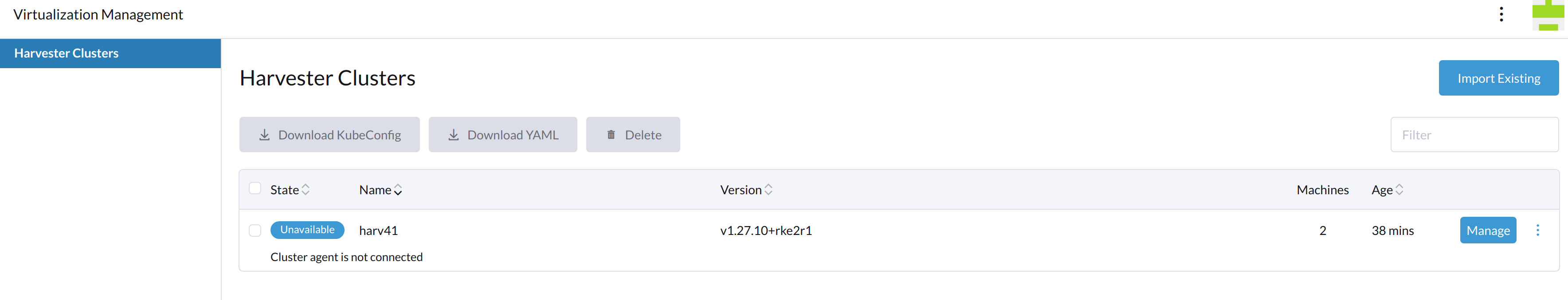
From now on, this Harvester is Unavailable on the Rancher Manager.
The Harvester WebUI returns 503 Service Temporarily Unavailable, all operations below can be done via kubectl.
Shutdown VM from the VM shell (e.g. Linux shutdown command).
Check the vmi instances, if any is still Running, stop it.
harvester$ kubectl get vmi
NAMESPACE   NAME   AGE    PHASE     IP            NODENAME   READY
default     vm1    5m6s   Running   10.52.0.214   harv41     True


harvester$ virtctl stop vm1 --namespace default
VM vm1 was scheduled to stop

harvester$ kubectl get vmi -A
NAMESPACE   NAME   AGE    PHASE     IP            NODENAME   READY
default     vm1    5m6s   Running   10.52.0.214   harv41     False


harvester$ kubectl get vmi -A
No resources found

harvester$ kubectl get vm -A
NAMESPACE   NAME   AGE   STATUS    READY
default     vm1    7d    Stopped   False
The volumes should be in state detached, check the related workload if some volumes are still in state attached.
harvester$ kubectl get volume -A
NAMESPACE         NAME                                       DATA ENGINE   STATE      ROBUSTNESS   SCHEDULED   SIZE          NODE     AGE
longhorn-system   pvc-3323944c-00d9-4b35-ae38-a00b1e8a8841   v1            detached   unknown                  5368709120             13d
longhorn-system   pvc-394713a4-d08c-4a45-bf7a-d44343f29dea   v1            attached   healthy                  6442450944    harv41   8d    // still attached and in use
longhorn-system   pvc-5cf00ae2-e85e-413e-a4f1-8bc4242d4584   v1            detached   unknown                  2147483648             13d
longhorn-system   pvc-620358ca-94b3-4bd4-b008-5c144fd815c9   v1            attached   healthy                  2147483648    harv41   8d    // still attached and in use
longhorn-system   pvc-8174f05c-919b-4a8b-b1ad-4fc110c5e2bf   v1            detached   unknown                  10737418240            13d
If your cluster has one Witness Node and the etcd leader happens to be on this node.
harvester$ kubectl get nodes -A
NAME     STATUS     ROLES                       AGE    VERSION
harv2    Ready      <none>                      25d    v1.27.10+rke2r1  // worker node
harv41   Ready      control-plane,etcd,master   55d    v1.27.10+rke2r1  // control-plane node
harv42   Ready      control-plane,etcd,master   55d    v1.27.10+rke2r1  // control-plane node
harv43   Ready      etcd                         1d    v1.27.10+rke2r1  // witness node

+------------------------------+------------------+---------+---------+-----------+------------+-----------+------------+--------------------+--------+
|           ENDPOINT           |        ID        | VERSION | DB SIZE | IS LEADER | IS LEARNER | RAFT TERM | RAFT INDEX | RAFT APPLIED INDEX | ERRORS |
+------------------------------+------------------+---------+---------+-----------+------------+-----------+------------+--------------------+--------+
| https://192.168.122.141:2379 | c70780b7862269c9 |   3.5.9 |   34 MB |     false |       true |        46 |    6538829 |            6538829 |        |
| https://192.168.122.142:2379 | db04095b49eb5352 |   3.5.9 |   34 MB |     false |       true |        46 |    6538829 |            6538829 |        |
| https://192.168.122.143:2379 | a21534d02463b347 |   3.5.9 |   34 MB |      true |      false |        46 |    6538829 |            6538829 |        |
+------------------------------+------------------+---------+---------+-----------+------------+-----------+------------+--------------------+--------+
Run kubectl delete pod -n kube-system etcd-name command to delete the etcd pod on the witness node to trigger the pod replacement and leader re-election so that the etcd leader will be located on one of the control-plane nodes. Check the etcd leader again to make sure.
If the Harvester cluster has been moved to a new location, or has been off for days, or your infrastructure has changes, check and test the network stability.
5.1 Restart the Control-plane Nodes and the Witness Node
The first step is to start those etcd located nodes one after another.
Power on the last shutdown node first. After about three minutes, continue the next step.
When you check the etcd pod log on this node, the following message may be observed.
sent MsgPreVote request to db04095b49eb5352 at term 5

"msg":"prober detected unhealthy status","round-tripper-name":"ROUND_TRIPPER_RAFT_MESSAGE","remote-peer-id":"db04095b49eb5352","rtt":"0s","error":"dial tcp 192.168.122.142:2380: connect: no route to host"
The etcd is wating for the other two members to be online and then vote a leader.
Restart the Rest of Control-plane Nodes and the Witness Node
Power on the rest nodes which also hosted the etcd pod before.
Wait until all the three control-plane nodes or possibly two control-plane and one witness nodes are Ready.
From CLI:
harvester$ kubectl get nodes -A
NAME     STATUS   ROLES                       AGE   VERSION
harv41   Ready    control-plane,etcd,master   54d   v1.27.10+rke2r1
harv42   Ready    control-plane,etcd,master   54d   v1.27.10+rke2r1
harv43   Ready    control-plane,etcd,master   54d   v1.27.10+rke2r1
The etcd forms a quorum and can tolerant the failure of one node.
note
If the embedded Rancher was not scaled down before, this step can also be:
The following EXTERNAL-IP should be the same as the VIP of the Harvester cluster.
harvester$ kubectl get service -n kube-system ingress-expose
NAME             TYPE           CLUSTER-IP     EXTERNAL-IP       PORT(S)                      AGE
ingress-expose   LoadBalancer   10.53.50.107   192.168.122.144   443:32701/TCP,80:31480/TCP   34d
Harvester deploys some basic components on the following namespaces. When a bare-metal server is powered on, it may take upto around 15 minutes for the Harvester OS to be running and all the deployments on this node to be ready.
If any of them continues to show the status like Failed/CrashLoopBackOff, a troubleshooting is needed to confirm the root cause.
If any of Longhorn PODs continues to show the status like Failed/CrashLoopBackOff, do not execute the following steps as many of them rely on the Longhorn to provision persistant volumes for running.
When the Storage Network has been enabled on the cluster, follow those steps to check if the Longhorn PODs have the correct second IP assigned to them.
After the Harvester cluster is re-connected to the Rancher Manager successfully, the Rancher Manager will handle the downstream K8s clusters' machines(vms) automatically. Wait until all the downstream clusters are ready.
Generate a new support-bundle file on the Harvester cluster.
Together with the previously generated support-bundle file, the two files record the cluster settings, configurations and status before shutting down and after rebooting. It is helpful for troubleshooting.
Harvester does not allow you to change the cluster token even if RKE2 is a core component of Harvester.
The RKE2 documentation states that the November 2023 releases of RKE2 (v1.28.3+rke2r2, v1.27.7+rke2r2, v1.26.10+rke2r2, and v1.25.15+rke2r2) allow you to rotate the cluster token using the command rke2 token rotate --token original --new-token new.
During testing, the command was run on the first node of a cluster running Harvester v1.3.0 with RKE2 v1.27.10+rke2r1.
Rotate the token on initial node.
/opt/rke2/bin $ ./rke2 token rotate --token rancher --new-token rancher1

WARNING: Recommended to keep a record of the old token. If restoring from a snapshot, you must use the token associated with that snapshot.
WARN[0000] Cluster CA certificate is not trusted by the host CA bundle, but the token does not include a CA hash. Use the full token from the server's node-token file to enable Cluster CA validation.
Token rotated, restart rke2 nodes with new token
When the first cluster node was rebooted, RKE2 service was unable to start.
RKE2 log:

...
May 29 15:45:11 harv41 rke2[3293]: time="2024-05-29T15:45:11Z" level=info msg="etcd temporary data store connection OK"
May 29 15:45:11 harv41 rke2[3293]: time="2024-05-29T15:45:11Z" level=info msg="Reconciling bootstrap data between datastore and disk"
May 29 15:45:11 harv41 rke2[3293]: time="2024-05-29T15:45:11Z" level=fatal msg="Failed to reconcile with temporary etcd: bootstrap data already found and encrypted with different token"
May 29 15:45:11 harv41 systemd[1]: rke2-server.service: Main process exited, code=exited, status=1/FAILURE
...
Do not attempt to rotate the RKE2 token on your cluster before Harvester announces official support for this feature (even if the embedded RKE2 binary has the token rotate option).
Harvester has a webhook that checks this setting to ensure it meets all conditions, e.g. the internal IPs and CIDRs are specified in the noProxy field.
note
Avoid changing the HTTP proxy from files in the host /oem path for the following reasons:
You must manually change the HTTP proxy on each node.
Contents of local files are not automatically populated to new nodes.
Without help from the webhook, some erroneous configurations may not be promptly detected (see Node IP should be in noProxy).
Harvester may change the file naming or content structure in the future.
Harvester is built on top of Kubernetes, RKE2, and Rancher. RKE2 generates a list of *.crt and *.key files that allow Kubernetes components to function. The *.crt file expires after one year by default.
$ ls /var/lib/rancher/rke2/server/tls/ -alth

...
-rw-r--r-- 1 root root  570 May 27 08:45 server-ca.nochain.crt
-rw------- 1 root root 1.7K May 27 08:45 service.current.key
-rw-r--r-- 1 root root  574 May 27 08:45 client-ca.nochain.crt
drwxr-xr-x 2 root root 4.0K May 13 20:45 kube-controller-manager
drwxr-xr-x 2 root root 4.0K May 13 20:45 kube-scheduler
drwx------ 6 root root 4.0K May 13 20:45 .
drwx------ 8 root root 4.0K May 13 20:45 ..
-rw-r--r-- 1 root root 3.9K May 13 20:40 dynamic-cert.json
drwx------ 2 root root 4.0K May 13 20:39 temporary-certs
-rw------- 1 root root 1.7K May 13 20:39 service.key
-rw-r--r-- 1 root root 1.2K May 13 20:39 client-auth-proxy.crt
-rw------- 1 root root  227 May 13 20:39 client-auth-proxy.key
-rw-r--r-- 1 root root 1.2K May 13 20:39 client-rke2-cloud-controller.crt
...
-rw-r--r-- 1 root root 1.2K May 13 20:39 client-admin.crt
-rw------- 1 root root  227 May 13 20:39 client-admin.key
...


$ openssl x509 -enddate -noout -in /var/lib/rancher/rke2/server/tls/client-admin.crt

notAfter=May 13 20:39:42 2025 GMT
When a cluster has been running for over one year, Kubernetes components may fail to start after upgrades or node rebooting. The workaround is to delete the related files and restart the pod.
Harvester v1.3.0 added the setting auto-rotate-rke2-certs, which allows you to set the Harvester cluster to automatically rotate certificates for RKE2 services. When you enable the setting and specify a certificate validity period, Harvester automatically replaces the certificate before the specified period ends.
note
Enabling this setting on your cluster is highly recommended.
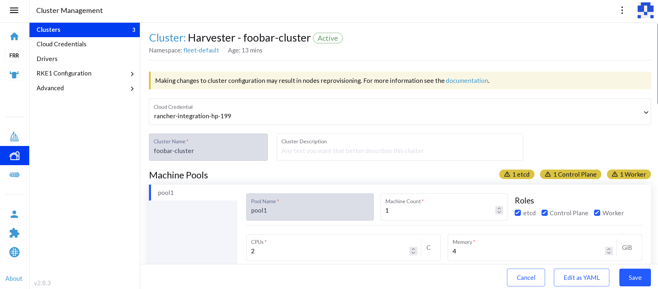
A side effect of using this default value is the expiration of authentication tokens embedded in kubeconfigs that Rancher uses to provision guest Kubernetes clusters on Harvester. When such tokens expire, Rancher loses the ability to perform management operations for the corresponding Rancher-managed guest Kubernetes clusters. Issue #44912 tracks the issue described in this article.
note
The issue affects only guest Kubernetes clusters running on Harvester that use cloud credentials created after installing or upgrading to Rancher v2.8.x.
You can patch the expired Harvester cloud credentials to use a new authentication token.
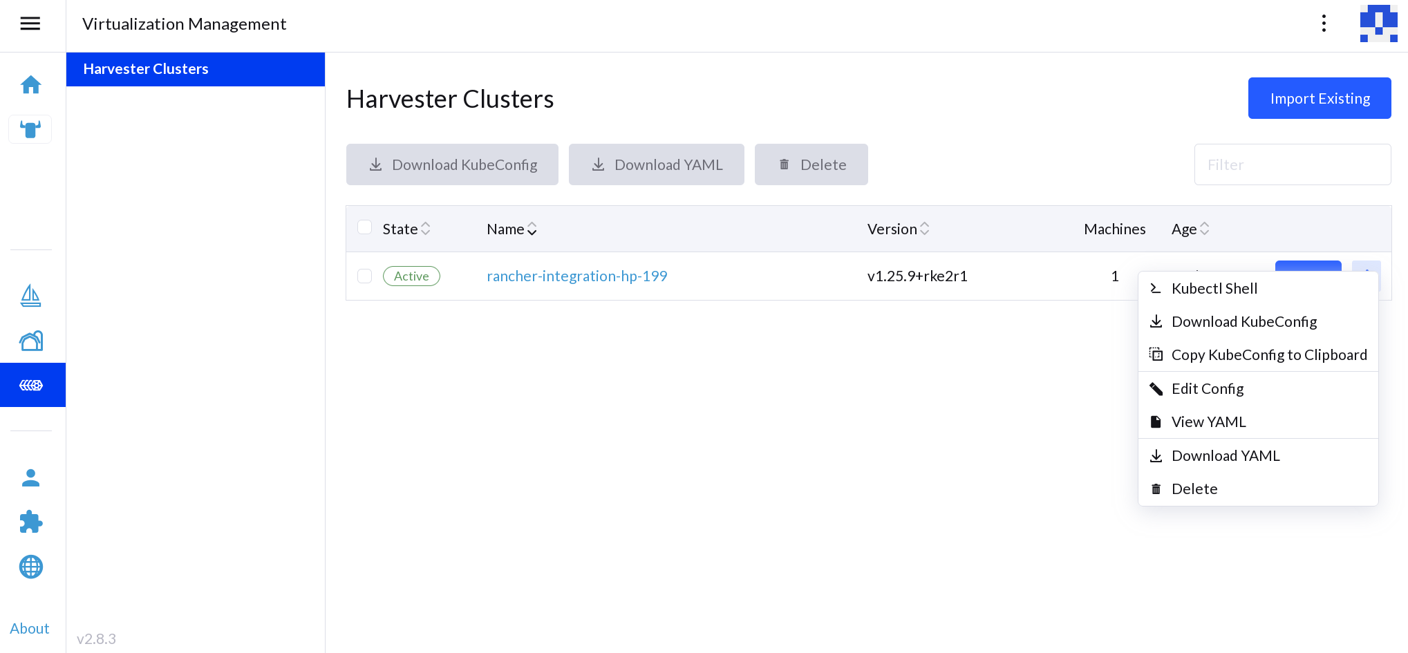
Identify the expired cloud credentials and which Harvester cluster is
affected by them.
Download a new kubeconfig file for the affected Harvester cluster.
Patch the cloud credentials. The cloud credential is stored as a secret in cattle-global-data namespace, and can be replaced with the new kubeconfig file. Ensure that the environment variable KUBECONFIG_FILE contains the path to the new kubeconfig file.
#!/bin/sh CLOUD_CREDENTIAL_ID=$1# .metadata.name of the cloud credential KUBECONFIG_FILE=$2# path to the downloaded kubeconfig file kubeconfig="$(base64 -w 0"${KUBECONFIG_FILE}")" patch_file=$(mktemp) cat>${patch_file}<<EOF data: harvestercredentialConfig-kubeconfigContent: $kubeconfig EOF kubectl patch secret ${CLOUD_CREDENTIAL_ID} -n cattle-global-data --patch-file ${patch_file} --type merge rm${patch_file}
important
macOS users must use gbase64 to ensure that the -w flag is supported.
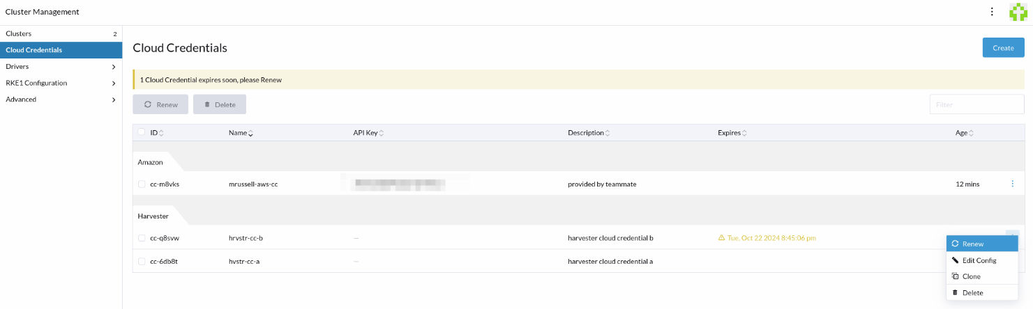
In Rancher 2.9.3 the Rancher UI displays a warning when a Harvester cloud credential or a related cluster contains an expired token. You can renew the token on the Cloud Credentials screen by selecting ⋮ > Renew, or the Clusters screen by selecting ⋮ > Renew Cloud Credential
note
When you upgrade Rancher, the Rancher UI does not display a warning for Harvester cloud credentials that expired before the upgrade was started. However, you can still renew the token on the Cloud Credentials or Clusters screen.
Expiration of kubeconfig Tokens in Rancher 2.9.4 and later versions
As previous versions, however now all expired Harvester cloud credentials will display a warning regardless of Rancher upgrade history.